High demands are imposed on safety-oriented process industry applications because of their enormous importance for personnel, plants, and the environment. Safety relays act as the connecting link between the control panel and the load circuit, and play a pivotal role in maintaining the “safety integrity level” of a system over the entire duration of its rated life cycle. The loads include both inductive and capacitive components and devices. Safety relays can also be used for various applications such as DTS (de-energized-to-safe) and ETS (energized-to-safe). In a DTS signal circuit, e.g., with emergency shut-down valves or motor controls, the open contact is the safe state; in an ETS signal circuit, the closed contact is the safe state. ETS circuit applications include e.g., optical and acoustic signaling devices, as well as extinguishing pumps. Pepperl+Fuchs has developed a new safety relay to optimize the availability of safety functions for process industry applications. It features fault detection for switching elements, integrated diagnostics, and line fault detection for field-side short circuits and lead breakages.
MooN Architecture vs. Force-Guided
Most commercially available safety relays are based on the principle of forceguided contacts. They feature an additional auxiliary contact that is always in the same position as the switch contact, and that provides feedback on its status. This requires separate wiring. However, the main disadvantage of the force-guided solution is that the field device can no longer be switched on or off should the switch contact itself fail. The problem is compounded yet further in the case of ETS process industry applications. Particularly at a low demand rate, feedback from the auxiliary contact does not necessarily mean that a current is flowing in the load circuit. This is because an emergency requiring a safe switch-on may not occur for years at a time in a process engineering setting, and the contacts often become contaminated or corroded in the meantime. This increases resistance and may mean that the safety function is no longer available when it is needed, even if the auxiliary contact confirms that a conductive connection has been established.
The safety relays newly developed by Pepperl+Fuchs therefore feature redundancy for all of the contacts to increase the availability of safety functions. The design is based on “MooN architecture;” M-out-of-N elements must be in an operating state. For the new safety relay with a 1oo3 architecture, this means that of the three integrated elementary relays, only one is used for the switching operation. These three relays are connected in series in the safety relay for DTS applications. For applications requiring ETS signal circuits, however, two groups of three relays connected in parallel are integrated to guarantee that all poles are disconnected.
Even if two contacts in a group fail, the safety function continues to be available. When used for DTS applications, the newly developed safety relay also features built-in protection against the welding of contacts and allows simplified proof tests that take up significantly less time than was previously the case. These tests must be performed at regular prescribed intervals to guarantee the availability of safety system components.
Integrated Diagnostics
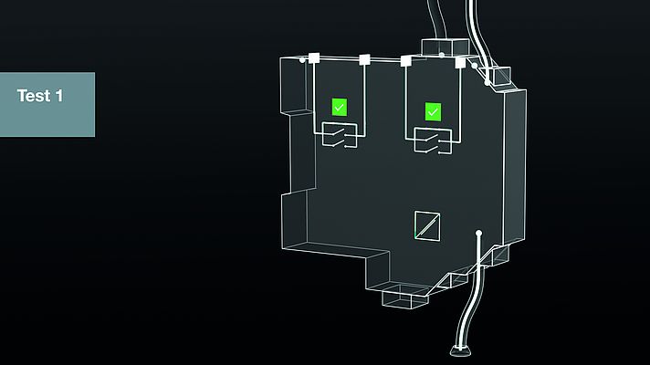
Users of the newly developed safety relay also benefit from integrated diagnostics that allow potential faults to be detected before failure. Diagnostics are performed by means of time-delayed switching of the elementary relays, with one relay being checked during each switching operation. In ETS circuits, all three relays of both contact groups are initially closed if three consecutive switching operations occur. During the delay period, the device checks whether this operation closes the circuit as a way of detecting a faulty contact. By changing the sequence for time-delayed switching, all contacts are checked after three switching operations. Diagnostic checks of DTS circuits take place during the restart process rather than during shutdown. Initially, two relay contacts are closed simultaneously, then the third contact is closed after a time delay. The idea is that there is no current flowing before this contact closes, otherwise this relay is faulty because it no longer disconnects the circuit. A different relay is checked during every switching cycle.
The checks are typically carried out annually. The safety relay executes the routine described above once during these annual tests and will have been fully tested after three years without any additional effort.
Line Fault Transparency
A safety function may not be available even if a safety relay is working properly. Potential causes for such failures include line faults and short circuits on the field side. Particularly in the case of sensitive ETS applications, for example, the delivery of extinguishing agents, it is therefore essential to monitor the signal circuit on the field side. However, detection of a line fault from the control side via the galvanic isolation up to the field device is not readily possible using conventional solutions. Additional wiring via the module’s fault indication output is necessary.
By way of contrast, the line fault transparency of the new safety relay provides seamless monitoring of voltage and load resistance. It detects field-side short circuits and lead breakages and can assign them to a specific signal circuit. A line or load fault on the field side results in detuning of the module’s input impedance. This interrupts the test pulses sent by the control panel for checking purposes, and faults are reported back to the corresponding digital output, without the need for additional wiring. The immunity of many ESD and DCS systems to test pulses is relevant in this regard. Thought was also given to the need for quick adjustments of the safety relay. The input circuit is identical for all devices. This means that once a device has been tested using one of the control panel’s DO cards, all other modules of the new safety relays are also compatible.
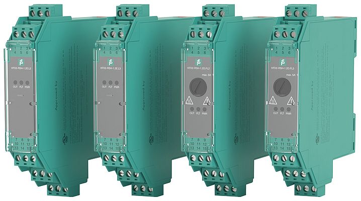
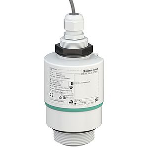
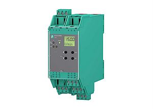
The complete product family of the new single-channel and loop-powered safety relay KFD2-RSH in a 20 mm-wide housing includes a total of four modules for DTS and ETS applications with either 24 VDC or 230 VAC. They are approved for ATEX Zone 2 (24 V version), and comply with SIL 3 (IEC 61508 ed2) and PL e (EN/ISO 13849 for the DTS module).


