The evolution of the geographical distribution of industrial activities, combined with an overall increase in capacity, and the concentration of the production in few large plants, made logistic management of industrial products more complex. A typical example is represented by the steam cracking for the production of propylene and ethylene: in the 70’s the average size was about 300 ktpa, and the plants were built in the same site where the product was used (for the production of polyethylene, propylene, PVC…), while current typical size is more than 1000 ktpa, and mostly located in oil exporting countries.
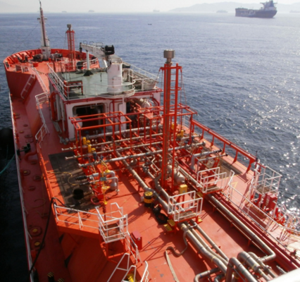
Among the available means of transport, marine shipping certainly occupies a dominant position for the movement of large amounts of bulk products. A particular case is related to the ships dedicated to the transport of liquefied gases (LPG, LNG, ...). These ships, in fact, are often equipped with an on-board liquefaction plant. The plant has both the function of keeping the storage pressure within the allowed vessel design limit and respect the commercial specification of products mainly as regards the temperature (Fig.1).
Liquefied gas carriers are usually grouped in the following categories:
- Fully pressurized. The simplest type of gas carrier, are usually equipped with 2 or 3 pressurized vessels (about 12-18 Barg) working at room temperature. They do not include any liquefaction plant, and thus storage pressure varies depending on cargo. These ships range in capacity from 500 to around 60000 m³;
- Fully refrigerated. Ship designed to transport liquefied gas at low temperature and atmospheric pressure. On-board liquefaction plant maintains these conditions. The typical capacities range from 20000 m³ to 200000 m³ and over. Large LPG/LNG carriers belong to this category;
- Fully refrigerated and Semi-pressurized. A combination of both the previous category. The typical capacity of this category is 2000 m³ to 20000 m³.
Given the big versatility of the latest category, it can be divided into the following groups:
- LPG carriers (-48 °C) in which the liquefaction of the boil-off vapors is achieved by condensation with seawater;
- LEG (liquefied Ethylene Gas) carriers (-104 °C). These ships descend from the previous category but equipped with a second refrigeration system for the liquefaction of ethylene, ethane and, in particular conditions, carbon dioxide. The availability of two refrigeration systems increases the versatility of this type of ship: the condensation of the vapor occurs at -40 °C.
From the engineering point of view, the installation of an industrial plant on-board of a ship presents some specific issues that affect both the design and the operation/maintenance of the plant itself. Primarily, the ship should be able to offer enough flexibility to meet the possible evolution of transport needs. It is therefore not uncommon that the same vessel can carry several products simultaneously (the transported substances are often flammable and sometimes toxic). The limitation of the space available for the plant is another factor that characterizes this type of installation.
On-board processes (inertization, gassing-up, loading, refrigeration/heating, unloading) are always discontinuous and occasional type. Furthermore, on board plants differ from production plants in cost factors: personnel for operations is widely available, energy has a negligible impact on total cost of operations, resources for maintenance lack. These factors require specific design, operation and maintenance criteria.
Design
To meet the needs of these applications, specific design approach is applied: the plant is conceived as multi-purpose, allowing the change of the plant scheme quickly and without the use of external resources. This allows keeping the dimensions of the plant within the limits set by the ship's geometry without affecting operation flexibility. It will also minimize the number of installed components. Proven and solid design machineries are selected, often regardless to efficiency.
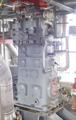
Vapor compression is the most critical operation, especially in the case of small ships, for which the compression system must be compatible with many chemicals, and the operative conditions varies depending on storage pressure. For the compression of boil-off vapors oil-free reciprocating compressors are employed. In order to limit maintenance, vertical compressors with labyrinth sealing, instead of piston rings, are selected. Often, due to space limitations, inter-stage coolers are not installed, but liquid injection is used to control temperature. Pumps for liquid transfer, generally with high flow to reduce discharge time, are usually multistage deep well type, with double mechanical seal.
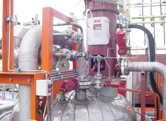
Shell and tube type heat exchanger made of corrosion-resistant materials (Titanium Gr.2 for seawater or AISI 316L for other uses) are preferred for the robustness and easy cleaning operations, although plate heat exchangers appear a very interesting alternative. Secondary, refrigeration groups are generally equipped with oil injected screw compressors with adjustable flow, which guarantee maximum reliability and minimum size. As refrigerant fluid, propane or propylene are commonly used.
Operation
The operation of the onboard plant requires a specific training, in relation to the hazardous nature of the fluids and to the sporadic nature of the operations.
Training is based on detailed procedures:
- Periodic test of ESD operation;
- Machinery integrity checks, with the removal of scaling and salt deposits, greasing and painting (due to aggressive environment);
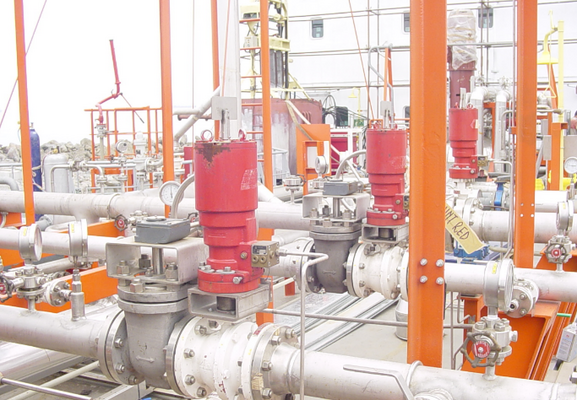
- Verify plant scheme for each operation (spool piece positions), using simplified plant diagrams;
- Periodic inspections of the plant and record of main plant parameters.
Maintenance
Within marine operations, maintenance interventions are generally very expensive: a complete gas-freeing is required (for those ships that transport flammable products all the plant must be first cleared, and then completely aerated). Maintenance activity on plant shall be performed within dedicated facilities, and the intervention of specialized technicians is often required. Taking in account ship downtime and related costs, maintenance operations are very expensive and must be planned in order to minimize the occurrence of plant failure while the ship is loaded and at sea.
Conclusions
As for on shore plants, onboard plants require a specific and detailed design, accurate procedures and a rigorous scheduling of maintenance operations. Maintenance activities planning and implementation of reliability improvements, have however a paramount role for onboard plants, both for the cost of ship availability and for the difficulties of facing a failure while in navigation with the ship fully loaded.
Author: Stefano Signorini , Technical Director at PECS S.r.l.


