Author: Daniel Hofer, Dipl. El.-Ing. FH and Bernhard Vetterli, Dipl. El.-Ing. HTL
Miniaturization in Pressure Measurement Technology
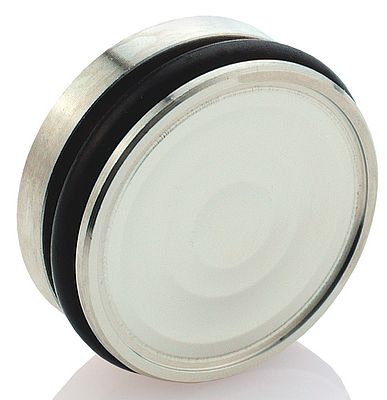
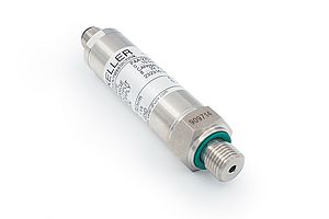
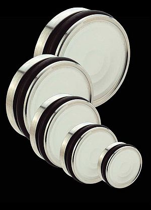
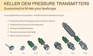
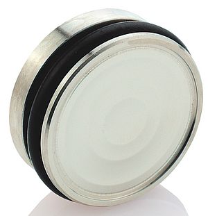
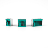
Keller‘s OEM transmitters are systems that can be described as „embedded“ in the best sense of the word – and in two different ways. First, the sensor and the downstream electronics are embedded in the same housing and second, the transmitter capsules themselves are ideally suited for embedding in application- specific systems. Depending on requirements, the output signal is standardized and temperature-compensated (ratiometric or digital).
Thanks to the Chip-in-Oil (CiO) technology developed at Keller, the trend toward sensor miniaturization is now a reality. This development can offer impressive advantages: an extremely compact structural design, high resistance to electrical noise fields and high vibration resistance thanks to low mass and short conduction paths.
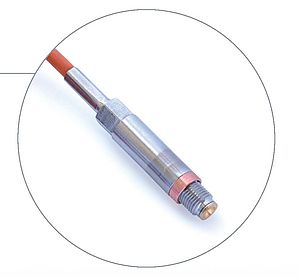
To put it clearly, CiO technology means that an ASIC is fitted directly next to the pressure sensor - in the same housing - to provide users with a whole range of beneficial functions. However, this does not make the pressure measurement capsule any larger: its external dimensions remain the same. This transmitter concept is available in housings 4L ... 9L, starting from a diameter of 11 mm.
Sintered-in pressure-resistant glass lead-throughs feed the transmitter signals outwards. The internal wiring uses short, lightweight bonding wires - with the total exclusion of air in oil. First, this approach eliminates the need to connect filigree signal processing boards with multiwire cabling in the rest of the installation process for the pressure transducer. And second, there is no need to protect the downstream electronics against moisture and condensation.
Together with the high-grade steel housing, the glass leadthroughs act as feedthrough capacitors, forming a Faraday cage. This makes the CiO technology
extremely resilient to electrical fields. Even field strengths of 250 V/m at frequencies of up to 4 GHz are unable to influence the measurement signal. The digital interface must be protected by the equipment manufacturer itself.
The ASIC is designed as a microcontroller with the corresponding peripherals, so the sensor signals can be registered with high resolution and dynamism. In addition to the process pressure as such, the temperature of the pressure sensor is measured and is used for mathematical temperature compensation when the signal is processed.
OEM transmitters supply two output signals: a ratiometric analog voltage output and a digital inter-integrated circuit interface (I2C).
Ratiometric output signal
The secret of the ratiometric format of the output signal is that it actually has no format at all, because it depends on the voltage supplied. This is an inestimable advantage for applications in integrated systems. If the analog-to-digital converter downstream of the transmitter is operated with the same supply voltage, the digital measured value will always be correct. This is because the height of the digitization steps depends on the voltage supply, but the number of steps does not – and their number is the critical factor. Using ratiometric signals substantially reduces the outlay on passing signals from the pressure transmitter to the A/D converter in the downstream electronics, and calibration steps are unnecessary; in the specific case of connection to a microcontroller with an integrated A/D converter, this outlay equals zero. Nevertheless, an interval is specified for the output signal, i.e. 0.5 ... 4.5 V for a supply voltage of 5.0 V. With a stable and precise supply voltage, this interval can also be used directly as the „standard signal“. The sampling rate of 2kHz offers amazingly good dynamic scope for a product based on the AD/DA principle. Moreover, the embedded electronics in CiO technology provide constant protection against overvoltage and polarity reversal on all lines up to ± 33 VDC.
Embedded Interface I2C
OEM transmitters that are the same size as pressure measurement capsules are never connected directly to field bus systems. Instead, the respective coupling modules have corresponding input interfaces, e.g. for the inter-integrated circuit or I2C interface. For years, this has been the serial standard to cope with short distances in embedded systems. The I2C master needs two lines for the serial data and the pulse (clock) for synchronous sampling. Consequently, no timing requirements are specified for the master - which, in fact, determines the timing. Each OEM transmitter has its own address, which is addressed by the I2C master. In the existing configuration, one master could manage 128 different addresses. The pressure and temperature values are registered by means of a request from the master, and are then available at the transmitters (slaves) after less than 4 ms, so that they can be clocked out according to a specified protocol. The values are temperature-compensated and –standardized, and they only need to be scaled from the 15-bit integer to a pressure and/or temperature with units.


