With signatories representing almost 200 countries worldwide, the Paris Agreement emphasizes the need for countries to significantly reduce their industrial emissions to air to help limit global temperature increases to 1.5°C. Many industrialized nations have already made significant progress in tackling their emissions, while developing nations are also increasingly demonstrating their ability to achieve growth while minimizing their environmental impact. Several countries are demanding that polluting facilities and plants install Continuous Emission Monitoring Systems (CEMS) to meet strict new levels or monitor previously unaddressed pollutants. Introduced in 2018, the EU’s Medium Combustion Plant Directive (MCPD) fills the gap between large combustion plants and smaller appliances like boilers. Aimed at controlling emissions of sulphur dioxide (SO2), nitrogen oxides (NOX) and dust, it covers around 143,000 plants with a rated thermal input equal to or exceeding 1 Megawatt thermal (MWth) and less than 50 MWth. Another example is India, where companies across polluting industries from metal processing through to oil and pesticides, must now use CEMS to monitor a range of emissions including particulates, ammonia, sulfur dioxide, oxides of nitrogen, chlorine, hydrogen chloride and carbon monoxide.
A choice of techniques
When it comes to measuring stack emissions, operators have a choice of techniques, specifically extractive, in-situ and cross-duct, the respective merits of which are outlined below.
Extractive techniques
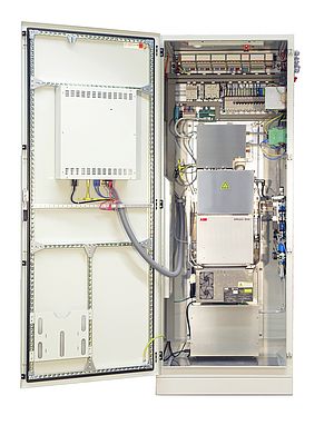
Extractive techniques are commonly used for gases. Extractive techniques consist of two main methods. Heated extraction involves extracting the sample gas from the stack using a sample probe, heated line, gas conditioning equipment and a heated sample pump. Before analysis, condensate is usually removed from the sample and the temperature is reduced to protect the analyzers, commonly referred to as “cold/dry” measurement. The alternative is to keep the gas hot all the way through the system, known as “hot/wet”. The sample must arrive at the analyzer inlet in a representative state that reflects conditions in the stack. The design of the sampling system must also protect against any sample loss or degradation. Several single component and multi-gas analyzers can be used with this method.
In-situ measurement
In-situ “probe” analyzers are directly connected to the probe installed at the measurement point. Most in-situ systems use infrared measurement techniques. While in-situ analyzers have the attraction of being installed directly on the stack with no sample handling, around 80-90 percent of plants worldwide have a strong preference for extractive methods, which tend to offer a lower cost of ownership. In comparison to in-situ measurement, extracting a sample means only the probe is in contact with the gas and not any delicate optical components. After conditioning, a clean and dry sample is presented to the analyzer. The system can then be installed in an air-conditioned cabinet or shelter, protecting against potentially harsh ambient conditions. Where in-situ devices are usually limited to one or two components, multiple components can be measured simultaneously using a sequence of sensors in an extractive system, requiring less holes in the stack. As the analyzer system is installed usually at ground level in a clean and accessible environment, maintenance is much more convenient, with components easy to work on and remove, and test gas cylinders are available nearby to easily calibrate the devices. Another popular technique is cross-duct analyzers, which project IR or UV (ultraviolet) energy across the stack and detect the change in energy state of the gas molecules as they absorb this energy at characteristic wavelengths. Most cross-duct systems measure one to two gases over a range of wavelengths. As they don’t come into contact with the target gases, they also need far less maintenance and operator involvement. One drawback is that cross-duct systems can be more complicated to calibrate, although this can be overcome using an automatic calibration system that can demonstrate accurate and reliable calibration checking.
Making operation easier
In the past, many operators have preferred to use single gas analyzers, believing them to be less complex and less prone to failure than systems that measure multiple gases. With the increased requirement for plants to monitor an expanded range of gas emissions, many users are using FTIR spectroscopy, which can measure multiple gases without needing frequent calibration. One example of where legislation is driving a requirement to measure multiple gases is China’s ‘Blue Sky’ legislation, which demands the measurement of a variety of parameters, including particulate matter, carbon monoxide, chlorine, oxides of nitrogen, sulfur dioxide, hydrogen chloride, and ammonia. Most of these can be monitored using modern FTIR gas analyzers and suitable data processing software. Systems that can measure multiple components can offer greatly reduced cost of ownership, with fewer detection elements and less equipment to maintain and calibrate. Calibration is a significant cost for CEMS operators, accounting for some 24 percent of operating expenses. It is needed for all types of gas analyzers, but the frequency of calibration can be much higher in some types than for others, with the US EPA, for example, requiring daily calibration. The effort and costs involved can also vary widely depending on the approach. One solution is to use internal gas filled cells. Proven to cut calibration costs by up to 95 percent, these cells are filled with a test gas of known concentration and are sealed to prevent them leaking, allowing them to offer a stable sample against which to test instrumentation performance. They are also accepted as a viable alternative to flowing test gas, meeting the requirements of both EN 14181 and US EPA 40 CFR part 60 regulations. An alternative is to use internal validation cells, which use films or cells for all FTIR components. Particularly suited to FTIR based CEMS, these cells conduct automated drift checks by rotating into the optical path to check precision and drift of all FTIR components. Digital solutions are also making their way into CEMS applications. The ABB Ability™ range of digital solutions, for example, enable operators to ensure regulatory compliance, reduce complexity and get the most from their CAPEX investments. These innovations include remote assistance. Allowing rapid problem solving, this solution cuts costs and downtime and reduces the training needs of staff. Remote Insights is a solution that makes maintenance safer and more effective, while features such as dynamic QR Codes allow the user to share diagnostic information to enable remote trouble shooting. Another development is remote condition monitoring using real time data. ABB’s condition monitoring system, for example, enables emissions equipment condition data to be relayed to its service experts for analysis. By allowing potential issues to be identified in advance, the risk of unplanned outages and downtime is reduced, providing system uptimes of 98 percent and enabling users to ensure continued compliance with availability requirements through optimum performance.
Change is in the air
As the impact of climate change becomes increasingly apparent, there is a growing awareness of the need for more stringent gas emissions monitoring. With new technologies that are more capable and accurate than ever and the support of vendors offering digital services to keep CEMS operational, keeping your emissions within limits has never been easier.
Author: Stephen Gibbons, Global Market Manager for Continuous Gas Analyzers for ABB Measurement & Analytics.


